Inductive subdermal power supply

got started on inductive power supplies today. it is only a very basic test but it worked somewhat ok so here is the thing.

i started with some old rfid components i had around. that means between 120 and 130 khz operating frequency.
build the following circuit. in my case i used  square signal from my function generator, it is 20Vpp with 50 Ohm output resistance.
transmitter coil is 60x30mm. so there is no need for ultra accurate positioning. used a led symbol as "load". 
forgive me my ktechlab circuit sketch but i figured it still looks better than my hand drawing (ok there aint one but who cares anyway)
image

the right half is the receiver side, used a small compact coil on a ferit core, 12mm long, 8 in diameter.

image

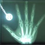
the coil surfaces are 15mm apart, putting the hand in between has no real noticeable effect.
the rectified output delivered a constant 1mA at 4V  (used a zener diode to limit the voltage). free running voltage goes up to 20 and more volts.
So this simple setup makes 4mW. i am rathar happy with it. it lights up an led quite nicely. 

good things:
•Using anohter 60x30mm coil for the receiver increases current to about 4mA, i got 0.8mA with a random one i found a switching power supply. so it is not all to critical to have a huge coil implanted, smaller ones seems to work reasonably well.
•frequency tuning can be performed on the transmitter, a multimeter is enough to do so. so no need for tuning the subdermal parts nor a need for expensive equipment.
•simple and cheap to build. no expensive or rare parts used so far. the square wave input can be done with a ne555 or some 74hc14, all standard parts. 

bad things:
•not maximized for range (i think there is no real need for now is 15mm between surfaces seems to be plenty)
•not very powerful (yet)

Opportunities here would be to swap the 1n4001 diodes (they have 1V drop voltage) with some lower voltage ones to increase the range to 2cm or maybe even a tad more.

next things to try:
• using higher frequencies to get higher currents
• try low Vf diodes
• try out a variety of receiver coils. especially flat ones.
• more powerful transmitter 

ultimate goal: charging a li-po cell with 10mA. that means, about 5 V and 10mA. that would allow for the southpaw battery to be charged in one night to run a week. i am confident.

Comments

  • edited May 2011
    What are the chances of tissue damage?  How long did you have your hand between the coils? 
  • edited May 2011
    tissue damage chance is zero. this is a magnetic field, a weak one. it is absolutely 100% save.

    addition, frequency tuning doesnt even require a multimeter. a coil+led is enough.
  • Haven't done the calcs on your components to see if you have done it already, but you can get much bigger distance/current by making both sides LC resonant circuits. The charger side can be quite a large area coil. However, you would need to drive it with a sine wave. (This might also be a legal requirement as sq waves have a lot of hi frequency components)
  • edited May 2011
    A lc resonator on the receiver indeed gives a better result for low loads. But with load it doesn't make that much of i difference (about 2 or 3mm). moving the coil a few mm closer or picking a slightly better coil will produce the same result. the whole thing is more like a very bad transformer rather than a regular antenna-receiver.
    so for now i went with the "low end" version as the benefits of simplicity outweigh the performance gain. 

    about the square wave thing.. it is true that square waves are not very clean but then it is only the driving input. the resonator itself is a rather good sine, see here ↓

    image

    scale is 5V/div and 1μs/div, with a 1/10 probe. voltage across the cap. and 2 leds as load directly soldered on the receiver coil. the input was a 20Vpp square with 50Ohm resistance. result: a pretty neat 300Vpp sine and 2 bright led's . without the receiver coil in it, i get about 350Vpp, with the same freq, if i tune to the unloaded resonance i get about 400Vpp. funny enough, i get better results (higher amplitude and thus better transmission with the square input).

    there still are some very small spikes on the peaks , they get more visible if you use a lower resistance driver. shouldn't be too much of a problem tho.
    i could drag it to my university's emv-lab and have it tested. intended to do that with the final circuit anyway.
  • Excellent that someone is actively working on the hardware, keep up the good work!
  • did some more experiments (read as: i was too lazy to calculate).
    came up with the following results.

    connecting more receiver coils in parallel sums up the current. at the same time it reduces the voltage so you lose some distance. once it reaches the threshold voltage of the 4,7V zener it jumps to 8mA with 10mm distance between coil edges. 15mA if i get really close.

    next thing for me to do. 
    •get 4 flat smd coils with about 4 to 10mH each, build a receiver array with it.
    •getting a better , more powerful transmitter coil. (maybe a small trafo magnet or so)
    •having a self-tuning transmitter really would help, it seems a bit tricky to find the sweet spot once the loads increase. so this 


    i start to feel that splitting the single functional parts into separate boards as i good idea. in southpaws case, one board with the inductive part and voltage regulator, one board with the battery and the charging controller, and the one with the magnetometer and μc. connected by flexible wires (and maybe a dynema string to keep forces away from the cable). so it would be easy to switch from triangular to a linear arrangement. it is less prone to breaking. easier to build and assemble. before implanting the whole thing gets a complete silicone coating (excluding electrode wire tips). it would also make the things very re-usable. 
  • i've got a blog post describing how to build an induction receiver that can use regular RFID readers as power sources. the one i've built can get enough power to run a microcontroller and LiPo recharger simultaneously, if it's close enough to the reader. i haven't tested how long it takes to recharge a completely drained battery like that yet though.

    basically, if you follow this guide with a few small adjustments, and use a 49mm 125kHz coil antenna, you can get a decent amount of power without having a purpose built transmitter. that antenna's bigger than i'd want implanted though, but smaller ones (like the 22mm one that same company sells) can't pick up as much power.

    ThomasEgi: how big would each board be compared to a single board with all the components on it? i agree that above a certain size, even just a couple of centimeters squared, it would be a good idea in order to reduce the chance it'd get broken. but, wires connecting multiple boards introduces more points of failure, and i can't imagine it'd make the implant operation any simpler. on the other hand, it does open up possibilities that other implants could use some of the same components easily.
  • nice links you got there. 
    on the receiver side i sorta favor smd coils as they are somewhat enclosed, come with a core, and they dont break as easy as a hair-thin wire.
    4 smd coils and a powerful trasmitter should do the trick.

    about the size.. i dunno. since it is a lot easier to manufactor and solder smaller boards with fewer parts, you can pack those parts more closely. but you lose some space by the fact that you need to connect them with some space. having some space between the units might be better for circulation and the skin. from what i can tell at the moment, each "pod" would be about 20 to 30mm in diameter, and between 3 and 6mm thick. for the southpaw that would be 3 of those.

    the connection between them can be reinforced. connect them with dynema strings and the wires will never be under tension. should last a lifetime. i found kevlar in my headphone wires. i sorta tortured those wires for 5 years, rolling over it with my chair, crashing down my keyboard etc. it is still fully operational so i am confident the same trick will work for us,too.

    true words about the implanting difficulties. placing the electrodes will be by far more difficult than anything else. so despite the potential trouble, i'd vote for modularity and go with multiple boards. if implanting becomes too difficult you can still build an applicator of some kind to ease it up.
  • you're right, SMD coils would be much better. have you got some picked out? here's a booklet which lists all the antennas some company called Premo make, and one or two of them look like they'd work well, the TP0602 in particular.

    and thanks for explaining those reasons for using multiple boards, it does sound like it'd be the best way to have the implant organized.
  • that particular coil is no good as we need them to be wound around the vertical axis. anything else would end up in tricky positioning for charging. i don't have any part numbers yet. but digikey stocks a whole bunch of suited ones.
Sign In or Register to comment.